ELECTRONIC SMART MODULE FOR LOAD SIMULATION AND FAILURE CONTROL OF LED INDICATORS
OUR UNIVERSAL SMART DUMMY LED LOAD MODULE (SLM) SOLVES ALL THE PROBLEMS THAT OCCUR WHEN REPLACING A CONVENTIONAL LAMP WITH AN LED.
Electronic Smart Load Module (SLM) Device solve LED Performance Issues with turning off all the way or flickering at specific dim levels and fix CAN BUS computer mistake.
WHY ARE INSTALLING LOAD RESISTORS FOR LED TURN SIGNAL LIGHTS?
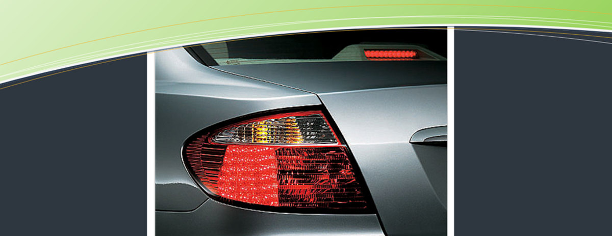
If you don’t install load resistors with LED turn signal bulbs, after replacing incandescent light bulbs to LED, you will experience the notorious hyper flash issue. Hyper flash the turn signal light flashes rapidly. LED bulb have a very low current draw so when they are used on a after replacing incandescent light bulbs, they may flash faster than usual, as if there was a blown bulb, or not flash at all (if there’s not enough ‘resistance’ to trigger the flasher relay)
HOW MANY LED LOAD RESISTORS DO YOU NEED?
You will need 1 Load Resistor for each LED lamp installed. If you will have glass and LED bulbs on one vehicle, you DO NOT need to add a load resistor to any glass bulb, ONLY LED.
A load resistor is generally required for each LED’s. To add a load resistor to an indicator (turn signal) it will need to be wired into each circuit in parallel and screw the load resistors to the radiator (vehicle body) so that the resistor does not burn out. The resistors can heat up to 170-180° C.
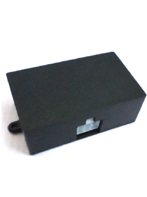
When you using our smart load module instead of a LED load resistor, the module SLM22112 (12 v) and SLM22124 (24 v) replaces 2 resistors with a capacity of 21 watts each, and the module SLM42124 (24 v) and SLM42112(12 v)replaces 4 resistors with a capacity of 21 watts each. The module does not heat up and therefore does not require installation on a radiator.
WHAT LOAD POWER IS NEEDED WHEN REPLACING TURN SIGNAL LAMPS WITH LEDS
When replacing a turn signal bulb with an LED, an additional 21 watt load is required. LED Dummy Load Resistors simulate a 21W globe in the circuit to rectify globe out messages & flash rate when using LED lights.
PROBLEMS THAT THE SLM MODULE SOLVES
When incandescent light bulbs are replaced by LEDs in the headlights of the car, vehicle On-Board Computer generates error because that LEDs consume less power. Additional to this error, the frequency of the turn signal is increased. To correct operation of the On-Board Computer or to prevent incorrect work of relays, we have to simulate a load equal to incandescent bulbs. Usually used for this purpose “LEDs load resistors” and “Dummy resistors“.
But those solutions have several serious disadvantages such as – inability of the On-Board Computer to detect LED’s failure due to load resistor and the overheating of the load resistors.
THE NOT HEATED SMART LOAD MODULE FOR LED (REPLACING STANDARD LOAD RESISTOR)
Usually when replacing ordinary lamps in cars with LEDs, used for this purpose “LEDs load resistors” or as they are also called “Dummy resistor“.
But those solutions have several serious disadvantages such as – inability of the On-Board Computer to detect LED’s failure due to load resistor and the overheating of the load resistors.
Our company has developed an innovative intellectual module” that solved those problems!
OUR DEVELOPMENT AND EXPERIENCE OF USE
Our smart module for LED indicators was developed through many years of experience supplying electronic devices to manufacturers and users of buses, coaches and trucks. Development was carried out in close collaboration with a major manufacturer of buses, taking into account the shortcomings of existing solutions on the market. Our module has been successfully used by bus manufacturers for over 10 years.
SMART LOAD SPECIFICATION
- Smart Module the module has two models 2 way and 4 way, for replacement 2 resistors X 21W or 4 resistors X 21 W
- Model SLM42124, has 4 way for replacing 4 lamps L/R with LEDs
- Model SLM22124, has 2 way for replacing 2 lamps L/R with LEDs
- Very compact , Dimensions 120x70x30mm
- Smart LED Load Module is very easy to install
- DC input voltage 12V, 24v
- Simulated Load per LED lamp 21W
- Weight 150g/ 180 g
COMPARISON TABLE BETWEEN THE USE OF LED LOAD RESISTOR AND OUR SMART LOAD MODULE
| COMPARISON TABLE |  | 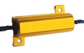 |
|
|---|---|---|---|
| 1 | Heating during operation | It doesn't heat up | Heats up to 170° C |
| 2 | Need for cooling, mounting to radiator | Not required | Requires mounting on radiator |
| 3 | LED load mounting | Easy installation | Complex installation on radiators |
| 4 | LED has burned out, failure message | There is an indication of a broken LED | If the LED burns out, but the resistor does not, there is no message. |
| 5 | Fix error message after replacing incandescent light bulbs to LED | Yes | Yes |
| 6 | Hyper flash or turn signal warnings caused by LED replacement bulbs. | Yes | Yes |
FEATURES
- Fix error message caused by On-Board Computer after replacing incandescent light bulbs to LED.
- The computer failure-control systems will work properly and detect LED’s headlights fault.
- SLM module is not heated and as a result it does not require a radiator and there is no need to mount it on a bracket to the car body.
- Low energy consumption does not load the electric system of the vehicle.
- Cancel Hyper Flashing on Turning Signal
- Reduces the likelihood of discharge, if for any reason the lights were not turned off.
- Compact, lightweight and easy to install
SMART LOAD 4 WAY 12V & 24 V MODULE INSTALLATION
CONNECTING:
The LED’s wire must be connected to pin OUT 1 – 4. The pin IN 1 – 4 must be connected to plus
signal wire. The power wire should be connected to the +24V source DIRECTLY, through its own fuse only. No other devices should be connected via this fuse !
10 – pin socket
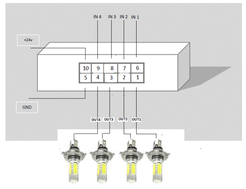
This block carries IN1 – IN4 light power signal inputs and four OUT1 – OUT4 simulate load outputs to LED headlight:
Pin 1: OUT1 – 24 watt simulate load output to LED
Pin 2: OUT2 – 24 watt simulate load output to LED
Pin 3: OUT3 – 24 watt simulate load output to LED
Pin 4: OUT4 – 24 watt simulate load output to LED
Pin 5: GROUND
Pin 6: IN1 – 24V light power signal input
Pin 7: IN2 – 24V light power signal input
Pin 8: IN3 – 24V light power signal input
Pin 9: IN4 – 24V light power signal input
Pin 10: + 24V input
SMART LOAD 2 WAY 12V & 24 V MODULE INSTALLATION
CONNECTING:
A LED’s wire must be connected to out 1 & out 2. The pin IN1 & IN2 must be connected to plus signal wire
The power wire should be connected to the +24V source DIRECTLY, through its own fuse only. No other devices should be connected via this fuse
6 – pin socket
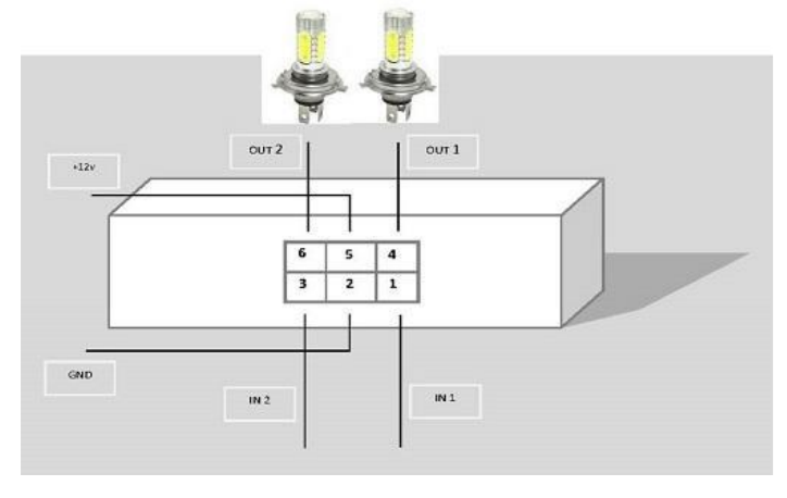
This block carries IN1 and IN2 light power signal input and two OUT1 and OUT2 simulate load output to LED headlight:
Pin 1: 12V or 24V IN1 light power signal input
Pin 2: Ground –
Pin 3: 12V or 24V IN2 light power signal input
Pin 4: OUT1 24 watt simulate load output to LED
Pin 5: + 24V input
Pin 6: OUT2 24 watt simulate load output to LED